Address
1903 US 49 Florence, MS 39073
Business Hours
Mon - Thu
9 a.m. - 4 p.m.
Friday
9 a.m. - 11 a.m. & 12:30 p.m. - 4 p.m.
Saturday-Sunday
closed
3D Cycle Parts started with a mission to make products that fix common problems on the KLR650. Our solutions have brought new life to many broken parts, made repairs more affordable, and improved durability in the process. Over the last few years we have added over 75 brands to our shop and we are in the process of expanding our selection to include riding gear, tires, and parts for other Adventure bikes! We are located in Jackson, Mississippi, USA and we ship anywhere within the USA. All products are in stock and ship daily unless the product page states otherwise. Thanks for visiting!
BRAKE PADS REPLACEMENT
The wheel does not have to be removed from the bike to replace the pads on either the front or rear of the bike. This is a relatively easy job, but the brake pads on the rear, especially, can be a little annoying.
FRONT Caliper
REAR Caliper
FRONT:
To start, this is not necessary, but you'll probably find it easier to replace the brake pads if the caliper is able to be moved freely about. If you choose to do this, you only have to remove the nut behind the reflector that holds the entire assembly to the tab on the fork tube - pointed to by the arrow in the above picture.
The caliper is held in place by two bolts, marked in the picture above by two red dots. Remove the bottom one, and then the top. Hold the caliper as you remove the top bolt so that it doesn't swing free.
The rear is shown in the photo above, but the idea is the same. It's my suggestion that you either hang the caliper by its frame in such a way that you can easily work on it, or that you have something like a 5 gallon pail available to lay the caliper on. Don't allow the caliper to just hang by the brake line, tie it up with rope or wire. On the front, I hung the caliper with a rope around it and the handlebars.
Shown above is the start of the procedure. Note the "legs" of the hairpin sticking out at the top of the "U" just above the Galfer text. That isn't a bolt, but rather a pin with a bolt head. Turn the pin until the head of the hairpin is sticking out and available - (as in the last picture of this front procedure) - and remove it with needle nose pliers, or whatever works best for you.
Pull the pin, soldier!
The picture above shows the pin being removed. When the pin has been removed, get a grip on the caliper mount and press the pads down to put the piston into a fully open position. This will take some effort, but not a tremendous amount.
Carefully apply a very light, even coat of grease to the pin to ease reinstallation.
The picture above shows the start of the pad removal. The piston is fully open, so the top pad can be swung out and removed from the mounting post.
NOTE: Look at the spring clip where the top pad rests, showed most clearly on the left side. Note that the ends are "L" shaped, the pad frame sits into the clip and into the "L" for correct operation.
The bottom pad comes up and out with a gentle push from the bottom.
The above picture shows the caliper with both pads removed.
NOTE: I've found that for a few years now I've had to slightly enlarge the hole in the pads because I couldn't get the pin through otherwise. Your experience may be different...
The bottom pad fits easily into place, and should be done now. As shown above, I found it was easier to line up both pad frame holes by inserting the pin into the bottom pad, and then holding the pad securely in place with my thumb.
Put the upper pad on the mounting post, remove the pin, and swing the upper pad into place. Make sure the upper pad frame is fitted correctly into the spring clip, resting in the "L" shaped arms.
Insert the pin down through the hole in the caliper and the two holes in the pad frames. Insert the hairpin.
The picture above shows the completed job. The piston will still be fully compressed, so it will be an easy job to slip the pads over the rotor.
I'd suggest blue Loctite on the caliper mounting bolts. Torque them to: 25 N-m, 2.5 Kg-m, 18 ft-lb
Remount the brake line holder if you removed it. I use a little blue Loctite on this, also. Just snug is correct.
REAR:
To provide free movement of the caliper, I suggest removing this rear line holder, as shown above.
Remove the two caliper mounting bolts, shown in the picture above, and marked with red dots. As with the front, remove the bottom bolt, and then hold the caliper as you remove the top bolt.
It's my suggestion that you either hang the caliper by its frame in such a way that you can easily work on it, or that you have something like a 5 gallon pail available to lay the caliper on, and work on it there. Don't allow the caliper to just hang by the brake line, tie it up with rope or wire.
The above picture shows the caliper at the start of the replacement. As with the front, you'll want to compress the piston as fully as possible to make the removal of the first pad - and later reinstallation of the pads over the rotor - easier.
The bottom pad is removed first, as shown above. It comes up with a push from underneath without too much trouble if the piston is fully compressed, which gives it room to get past the mounting plate and upper pad frame.
With the bottom pad out, the next thing to do is remove the upper pad. Put your thumbs on the plate in the middle, marked with the RED line. Put your hands on and around the caliper body, and push the plate down, in the direction of the YELLOW arrow.
You should now be able to slide the top pad up, and over the mounting posts. You may find it works best to get the pad off one post at a time using a slight rocking motion. If it doesn't come off, you need to compress that middle plate more.
Reinstallation is easier because everthing is already pretty much set the best way for it. Drop the lower pad into place, making sure you set it correctly into place.
Install the upper pad. Try moving it onto the two mounting posts all at once, or over one post at a time, rocking it slightly into place.
The above picture shows the completed installation of the pads. Note that with the piston still compressed, there is ample room for the pads to easily fit over the rotor.
Remount the caliper over the rotor, and torque the bolts to the appropriate value. (I'd suggest blue Loctite on the caliper mounting bolts.) Torque them to: 25 N-m, 2.5 Kg-m, 18 ft-lb
I like a small amount of blue Loctite on the screw that holds the brake line bracket in place. Just snug is correct.
I was extremely satisfied with the high quality products and services you provided. Each item was precisely what I expected. When I had questions, they were answered quickly and thoroughly. 3D Cycle parts is the kind of company that reminds me of a time when the customer mattered and the company went out of their way to earn their business. I have and will continue to recommend 3D Cycle Parts to others in the ADV and motorcycle community based on this experience.
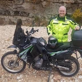
Tu Combs
Owner
3D Cycle Parts started with a mission to make products that fix common problems on the KLR650. Our solutions have brought new life to many broken parts, made repairs more affordable, and improved durability in the process. Over the last couple of years we have added brands like Eagle Mike, Dirtracks, Maier, Warp 9, Doubletake, Cyclops, Seat Concepts, JNS Engineering, and more aiming to be your one stop shop when it comes to KLR 650 maintenance and upgrades! We are located in Jackson, Mississippi, USA and we ship most products worldwide. All products are in stock and we ship daily unless the product description states otherwise. Please follow us on Facebook and Instagram and don't hesitate to email us if you have any questions. Thanks for visiting!
Business Hours
Mon - Thu
9 a.m. - 4 p.m.
Friday
9 a.m. - 11 a.m. & 12:30 p.m. - 4 p.m.
Saturday-Sunday
closed